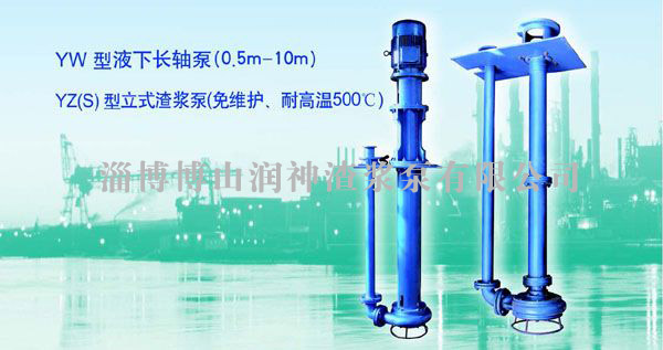
YW UNDERWATER LONG-SHAFT PUMP (0.5m-10m)
I, Summarize
YW Underwater Pump is the vertical centrifugal pump structure with single stage and single suction, as the semi-shrouded impeller of this series pump, there is the agitating vane on the vane extended for backflow agitation, machinery crushing and jamming prevented.
Two series pumps are mainly used in the environmental protection, the municipal engineering, the thermal power plant, the aeroconcrete, the coal coking plant, the refinery, the steel mill, the mining, the paper making, the cement plant, the foodstuffs factory, the printing and dyeing industries to pump thick liquid, thick oil, dreggy liquid, slurry, mortar, drafting sand and sludge in urban sewage channel, as well as mud and sand residue liquid and corrosive liquid. YW can also pump every kind of discharging to use from the human and animal��s excrement sewage, the large and medium size methane pool and the methane projects. YZ(S) may also transport kerosene, crude oil, asphalt and oil residue at high temperature (500��).
Model Meaning: eg.80YW80-20A
YW�CUnderwater multi-purpose sewage pump
80 �C Pump outlet diameter (mm)
80�CPump design flow rate (m ³ / h)
20 �CPump design head (m)
A �CImpeller first to be cut less
80��YZ80-20A
YZ (S) - Vertical slurry pump
80 �C Pump outlet diameter (mm)
80�CPump design flow rate (m ³ / h)
20 �CPump design head (m)
A �CImpeller first to be cut less
Pump��s drive type: The pump is connecting through the flexible coupling and the electric motor, the pump direction of rotation is clockwise from the prime move.
II, Structure introduction
YW Underwater Pump is the centrifugal pump structure with single stage and single suction, with the intermediate pipe connecting the pump hydraulic components and bearing body and supporting tray, the water is discharged out from the outlet pip parts, pump impeller is for semi-shrouded with the agitating vane on the vane extended, which can transport the medium of particles. The length of inserting the water by pump is 10m, When the underwater length is more than 1.5m, it must use the coupling shaft structure, and to install the rolling bearing (grease lubrication) with coupling shaft housing connection. The rolling bearing on the bottom of the pump is isolated with the mechanical seal and the liquid level, which can not contact the liquid. The pump bearing has the enough rigidity to guarantee the pump steady running, if runs in the deep well, may add a suction pipes (Give clear indication of in the contract).
YW Underwater Pump Structure
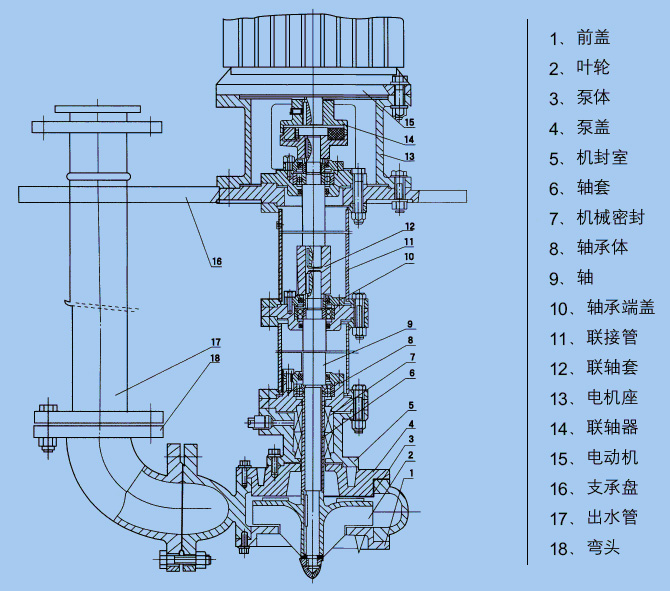
1��ǰ�� Front cover
2��Ҷ�� Impeller
3������ Pump body
4���ø� Pump cover
5�������� Mechanical sealing chamber
6������ Shaft liner
7����е�ܷ� Mechanical sealing
8������� Bearing body
9���� Shaft
10����ж˸� Bearing end cap
11�����ӹ� Intermediate pipe
12�������� Coupling shaft housing
13������� Motor cabinet
14�������� Coupling
15���綯�� Electromotor
16��֧���� Support tray
17����ˮ�� Outlet pipe
18����ͷ Elbow
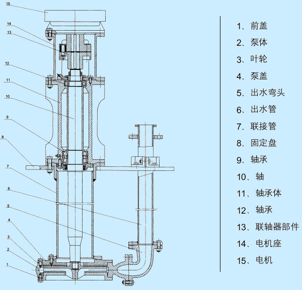
1��ǰ�� Front cover
2������ Pump body
3��Ҷ�� Impeller
4���ø� Pump cover
5����ˮ��ͷ Outlet elbow
6����ˮ�� Outlet pipe
7�����ӹ� Intermediate pipe
8���̶��� Fixed tray
9����� Bearing
10���� Shaft
11������� Bearing body
12����� Bearing
13������������ Coupling parts
14������� Motor cabinet
15����� Motor
Figure 1 YW Series Underwater pump structure chart
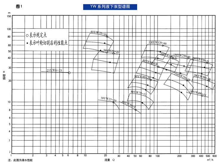
�� indicates standard point
�� indicates the performance point after impeller cutting
Note: This chart is clean water performance Flow rate Q
Head H
|
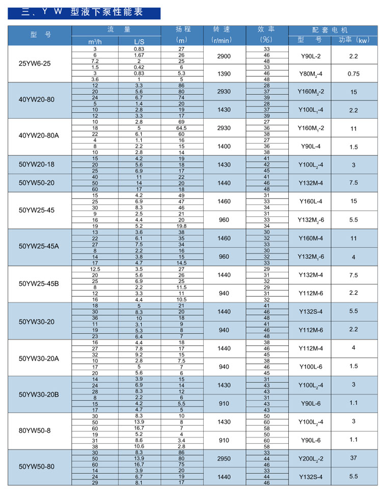
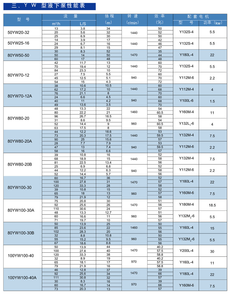
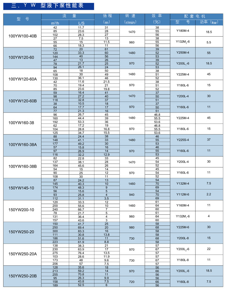
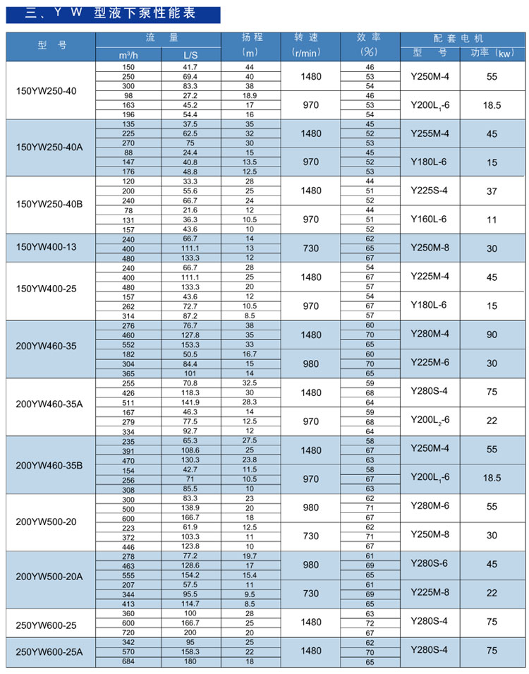
��YW Underwater pump performance table |
|
Model |
Flow rate |
Head
��m�� |
Rotate speed
��r/min�� |
Efficiency.
������ |
Assembly Motor |
|
m³/h |
L/S |
Model |
��KW��
Power |
V, Assembling and disassembling
YW Underwater pump assembly sequence
(1) To install the bearing in the bearing body.
(2) To install the oil-sealing felt rings separately in the bearing body and the bearing end.
(3) To embed the mechanical seal in shaft sealing.
(4) To install the bearing end cover near the mechanical seal on the shaft, to install the "O" ring, shaft sleeve and installed bearing lower bearing body on the shaft with screw to tighten bearing end cover, to install the intermediate pipe and shaft seal body on the upper and lower side respectively of the bearing body with screw to tighten, an then to screw the bearing end cover on the intermediate bearings, the bond is embed into the shaft, the coupling shaft housing is loaded on the shaft with upper shaft embed bond in the coupling shaft housing, the upper coupling pipe installs on the intermediate bearing with screw to tighten, the parts above should install on the supporting tray and the upper bearing body on the supporting tray with screw to tighten and bearing end cover to install.
(5) To install the pump cover on the shaft seal and to tighten with screw, to embed the impeller bond in the shaft and to install the impeller and the thrust washer in turn with impeller nut to fix, the pump body installs on the pump cover with screw to tighten, to install the front cover and to tighten with screw and pump body.
(6) To install the shaft coupling part on the upper shaft, and to fasten the motor shaft coupling with the fastening screw on the shaft head, the motor is connected tightly with motor seat.
(7) To install and to fix the asbestos cushion, the elbow and the outlet pipe on the supporting tray from the pump exit sequence.
��, Installation
1. The equipment work before installation.
a. To inspect whether the water pump and motor damaged
b. Preparation for tool and hoisting equipment
c. To inspect the foundation according to drawing.
2. To install the pump supporting base on the vessel and to tighten the screw (for example the cement well must establish foundation screw in advance).
��, Start up and stop
1. To observe whether the pump installation foundation already to be stable and whether all the parts screw already to be tight.
2. To inspect whether the pump axis gap already to adjust well (pulled coupling not have fricative).
3. Oil standard pours into the calcium base grease.
4. To inspect whether the electric motor rotation direction to be correct.
5. To start up the motor, to turn on the gauge meter, the gate valve should open the demand scope when the pump rotated entirely.
6. When pump stop working, it should stop the electric motor at first, then close the gauge meter.
7. The pump should stop running for a long term, should disassemble and clean the pump, wipe and preserve the antirust oil.
��, Operation
1. Pay attention to the pump bearing temperature, which should not surpass the environment temperature with 35��, but the highest temperature should be not bigger than 75��.
2. The lubricate cap should fill up the calcium base grease to guarantee the bearing can lubricate normally.
3. The pump should replace the electric motor supporting in works in the first month or work for 100 hours later, to replace for working every 2000 hours.
4. Periodic inspection of the flexible coupling, pay attention to the electric motor bearing temperature to rise.
5. In the running process, if to find the noise or unusual sound, which should stop the inspection immediately.
6. The pump should make the periodic inspection for every 2000 hours, the gap wear between impeller and pump body (pump cover) can not be too large, the gap maximum value does not surpass 1.5 mm, can replace the impeller or the front cover if surpassed.
����Common faults and removal method
|
Common faults |
Possible reason |
Removal method |
|
No water pumped, the pressure gauge pointer violent beating
|
1. Inlet pipe siltation
2. Pipe and instrumentation leakage
|
1. Remove the blockage
2.Block up the air leakage parts |
|
No water pumped |
1.Pump inlet higher than liquid level
2. Wrong rotating direction |
1.Heighten the liquid level or descend the pump installation height
2.Inspect motor swerve |
|
Gauge indicates there are some pressure on the outlet, where still not pump the water |
1.Outlet pipe resistance is large
2.Impeller siltation
3.Revolution deficiency |
1.Inspect the pipe
2.Clean impeller
3.Add pump revolution |
|
Flow rate over-lowing |
1.Water pump siltation
2.Revolution deficiency
3.Serious wearing in impeller |
1.Clean pump and pipe
2.Add the revolution
3.Change the impeller |
|
The pump consumed power is oversized |
1.Pump water supply is too small(or all closed)
2,Wearing in impeller |
1,Outlet pipe open the gate valve
2.Change the impeller |
|
Overheating in bearing |
1,Bearing oil starvation
2,Bearing feculence or damage |
1,Add lubrication
2,clean bearing or replace bearing |
|